The ES Switch Unit (ESSU) is a HWCI that provides the switching interface between the RF Subsystem 1 and the RF Subsystem 2. The major requirements of the ESSU are as follows:
- Provide RF switching to select either the RF Subsystem 1 or the RF Subsystem 2 to the Subsystem 1 Back End
- Provide PDW switching to select either the RF Subsystem 1 or the RF Subsystem 2 to the Subsystem 1 Back End
- Provide audio signal switching to select either the RF Subsystem 1 or the RF Subsystem 2 to the Subsystem 1 Back End
- Provide proper termination for the un-selected Subsystem
- Minimize the effect of the ESSU on the RF Subsystem 1 sensitivity and dynamic range performance, with minimized RF losses
- Provide signal conditioning, as needed, to interface the RF Subsystem 2 to the Subsystem 1 Back End. This could include amplification, attenuation, and equalization
- In the process of the signal conditioning above, the ESSU will minimize the degradation of the RF Subsystem 2 sensitivity and dynamic range
A block diagram of the ESSU is shown below
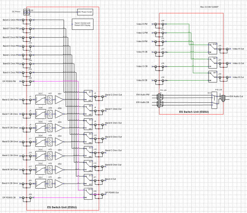
Some of the major components in the ESSU are as follows:
- Wideband RF/Microwave amplifiers
- Our Extreme BW RF amplifier was used in this design for the low frequency, wide bandwidth RF path
- Equalizers and attenuators to align the RF paths
- Some vendor purchased equalizers were used
- R. A. Wood Associates equalizers were also used where vendor equalizers were not available
- Terminated mechanical RF switches (50 ohms)
- Terminated mechanical RF switches (75 ohms)
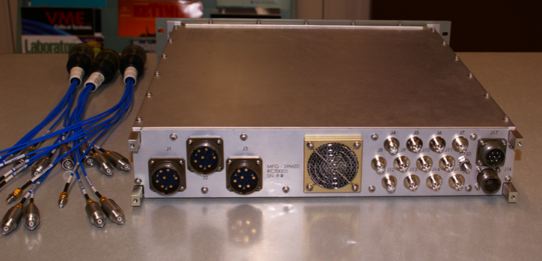
- HDRFI external RF interface to save RF connector space
- DC power conditioning
- FPGA card to control switches and provide Built-in-test (BIT) status
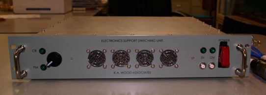
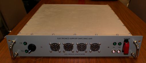
- LED displays for BIT and switching status
- Custom designed audio switching board
R. A. Wood Associates designed the mechanical assemblies using SolidWorks mechanical modeling program. The ESSU was a 2U rack-mountable assembly. Components were assembled to a center mounted RF plate. Cooling air was drawn in from front to back via rear mounted fans, and flowed across both sides of the RF plate.
An Acceptance Test Procedure (ATP) was developed, submitted, and approved by the Navy. A formal acceptance test was witnessed and passed all specifications. We used our automated RF testing software (RFSpecTest and Painless Extraction) to speed up the testing process so the ESSU could be fully tested, summarized and completed in 1 day.