Monday, May 06, 2013
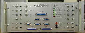
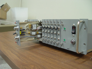
New Bench Top RF Switch Digital I/O Test Interface Box
|
The RF Switch/DIO Box is a custom designed LRU that provides:
We have built 5 of these for our own automated test stations. The
design is universal and can be used for multiple test applications.
|
Tuesday, March 05, 2013
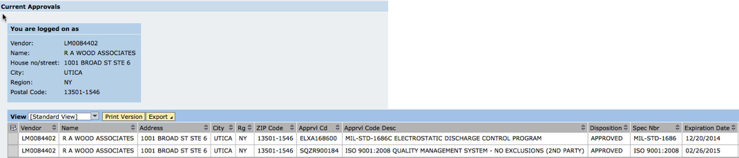
R. A. Wood Associates is approved for ISO 9001:2008 Quality Management System (2nd Party) and ESD Control!
Great News! R. A. Wood Associates has received approval by Lockheed Martin for ISO 9001:2008 Quality Management System (2nd Party survey), and Electrostatic Discharge Control (ESD). This puts us in a better position to deliver the highest quality products to our customers. Thanks to everyone involved who helped to make this become a reality! Bob Wood
Monday, June 04, 2012
Available Now! SimpleCycle Crystal Oscillators
We have officially released a new line of SimpleCycle crystal oscillators. These are temperature compenstated crystal osciillators in a very small package with +5 Volt DC in, and an SMA output connector. The key features include:
|
|
We will be working to supply these with very quick turnarounds. For more information see our SimpleCycle Oscillator page, or contact us.
Edited on: Tuesday, June 26, 2012 5:38 PM
Categories: 1 Engineering Consulting Services, 4 Hardware Products
Monday, January 30, 2012
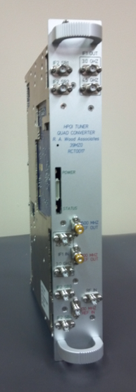
High Dynamic Range Microwave Tuner Designed and in Production
|
We haven't posted in a while. It's because we've been crazy busy. Our newest product, the RCT0017 WB Tuner and Quad Converter, has been under development over the past 2 years, and is now available. We've designed this from the ground up to meet state of the art high input compression point, low phase noise, fast tuning speed, wide dynamic range, and wide instantaneous bandwidth requirements. A quick overview of the specifications:
A brief data sheet can be downloaded from this link |
|
Edited on: Monday, June 04, 2012 7:26 PM
Categories: 1 Engineering Consulting Services, 4 Hardware Products
Wednesday, January 18, 2012
New Quad Converter Designed and Delivered
|
We designed and built for production a 4 channel Quad Converter.
Our Quad Converter design features:
This is a very complex design with very high density surface mount
assemblies. Surface mount assemblies are built using pick and
place machines at a contract manufacturer. Automated RF test rack,
fixtures and software has been designed at R. A. Wood Associates.
|
Wednesday, December 14, 2011
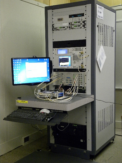
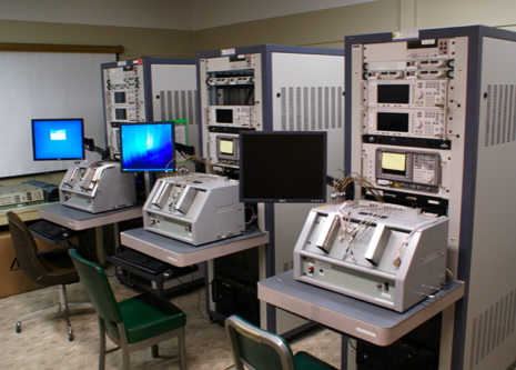
RCT0017 Automated RF/Microwave Test Station Designed, Built, and In Service
|
Edited on: Sunday, October 06, 2013 11:22 AM
Categories: 1 Engineering Consulting Services, 2 Software Products and LabVIEW Projects, 4 Hardware Products
Monday, November 14, 2011
LB RF Receiver Simulator Designed and Delivered
|
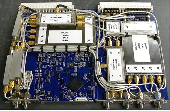
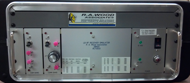
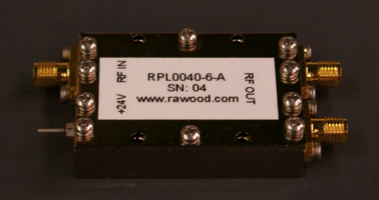
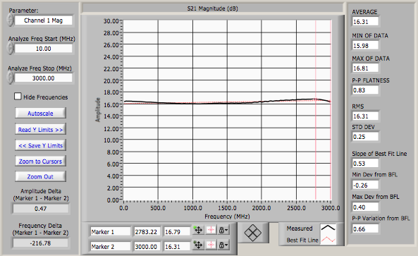
| A LB RF Receiver Simulator was designed to simulate the RF front end of a submarine periscope subsystem. The noise figure, gains, and dynamic ranges were designed to simulate the actual subsystem. The amplifiers were custom designed and equalized by R. A. Wood Associates to cover a wide bandwidth from ~DC to 3 GHz. A variable attenuator allowed the output noise floor to be adjusted in 1 dB steps. |
Edited on: Thursday, January 31, 2013 2:22 PM
Categories: 1 Engineering Consulting Services, 4 Hardware Products
Monday, December 20, 2010
2nd Test Station Delivered to NAVSEA NSWC
We designed and built a 2nd (different) Automated RF Test Station
for NAVSEA NSWC, which was delivered to Crane, Indiana. This Test
Station contains many state of the art features and equipment,
including:
|
|
Edited on: Sunday, October 06, 2013 11:51 AM
Categories: 1 Engineering Consulting Services, 2 Software Products and LabVIEW Projects, 4 Hardware Products
Saturday, May 08, 2010
New Equalizer Designs added to our Product Line
|
We've released some new equalizer designs in the past few months:
For more information and test results, visit or "Equalizers on Demand" WWW page. If you don't see a design that fits your needs, please call us and we'll try to develop a design that meets your requirements. Thanks for all your support, equalizer users! |
|
Test Station Delivered to NAVSEA NSWC
|
We delivered a Test Station to NAVSEA Naval Surface Warfare Center (NSWC) in Crane, Indiana. The Test Station contains many state of the art features, including:
This was a very exciting project, and we really enjoyed working with our customer on this program. The complete project was delivered within 7 months of the order being placed. Great job everybody! |
|
Edited on: Sunday, October 06, 2013 11:52 AM
Categories: 1 Engineering Consulting Services, 2 Software Products and LabVIEW Projects, 4 Hardware Products
Monday, April 05, 2010
mmW Equalizers Designed and Built for our Customer
|
One of our customers had a need for a mmW equalizer to help offset
a 7 dB negative slope across a 26.0 to 40.0 GHz band. We looked
far and wide to see if there were any available components out
there in the industry that we could buy as an off-the-shelf part,
or have someone develop for us.
We could not find any available parts. So we took on the task
ourselves to design a mmW equalizer with a 7 dB positive gain
slope. This is just another example of how we can break new ground
to come up with designs that are needed by our customers when they
are not otherwise available.
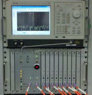
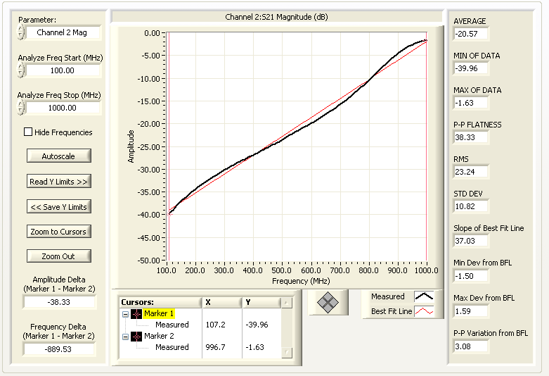
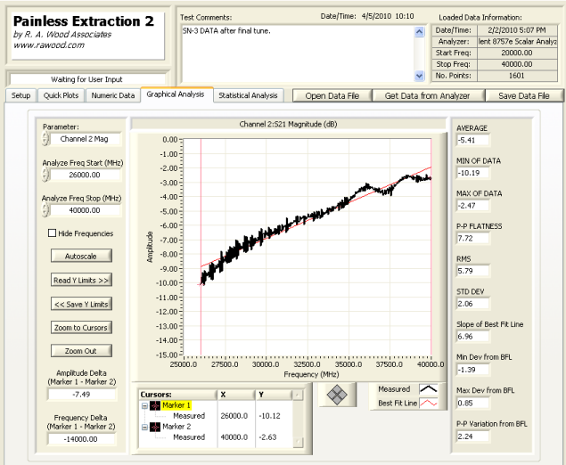
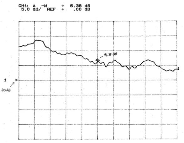
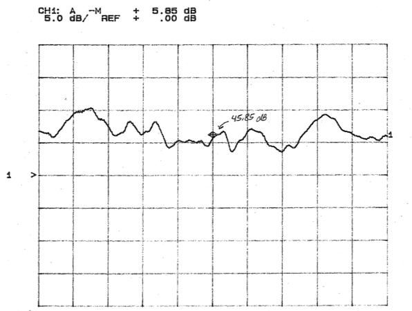
The equalizer was installed in the system, and the 7 dB negative
slope was flattened out. See before and after pictures below.
Another exciting success story!
|
|
| System RF Path Gain before equalization (26-40 GHz): | System RF Path Gain after equalization (26-40 GHz): |
|
|
Saturday, October 31, 2009
LB Modules SN #10 and 11 Ready for Delivery!
|
Our 10th and 11th LB RF modules, containing our Extreme BW RF amplifiers, have been built, and tested, ready for delivery to our customer. These modules will be used in our customer's systems, which will be installed on board Navy vessels. |
|
Edited on: Wednesday, November 18, 2009 2:42 PM
Categories: 1 Engineering Consulting Services, 4 Hardware Products
Monday, October 05, 2009
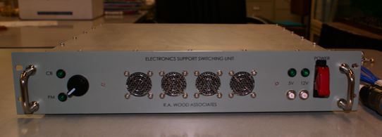
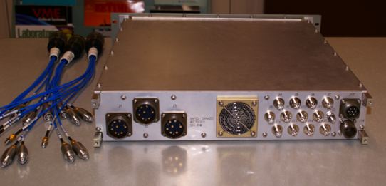
ESSU SN3 Delivered
|
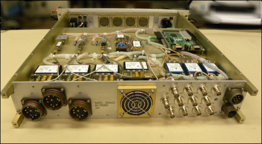
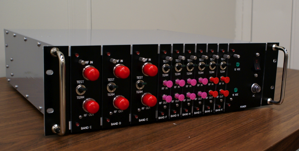
We've delivered the third Electronics Support Switching Uint (ESSU) for one of our customers (ahead of schedule!). This was another set of hardware slated to to be installed on a Navy Vessel. The ESSU is shown here with the cover removed, looking from the back. All RF components are mounted on both sides of a center RF plate. Shown are RF amplfiers, equalizers, attenuators, RF switches, cabling, FPGA card, and rear connectors (21 RF connectors, 12 video/75 ohm connectors, Audio, Power). For additional information, please visit our ESSU information page. |
|
Edited on: Thursday, November 05, 2009 8:44 PM
Categories: 1 Engineering Consulting Services, 4 Hardware Products
Tuesday, September 29, 2009
R. A. Wood Associates awarded contract from NSWC Crane Division
|
R. A. Wood Associates has been awarded a contract from Naval Surface Warfare Center (NSWC), Crane Division. The contract involves designing and delivering an automated test rack consisting of:
We are fortunate to be able to work with Viewpoint Systems on this contract.
This contract was won on a competitive bid, and our solution was selected out of many other submissions. We are very excited about the opportunity to work with NSWC Crane Division! |

|
Edited on: Sunday, October 06, 2013 11:53 AM
Categories: 1 Engineering Consulting Services, 2 Software Products and LabVIEW Projects, 4 Hardware Products
Friday, August 21, 2009
RF Receiver Simuator SN4 Delivered
|
We've delivered our fourth RF Receiver Simulator, and our 6th of a
family of Receiver Simulator products. The simulators are designed
to represent the RF front end (noise figure, gain compression point,
and intercept point) of a complex EW system, to allow testing,
verification and validation of the EW system back end, without
requiring the expensive front end components. If you have a need for one of these types of products, please contact us. |
Wednesday, July 08, 2009
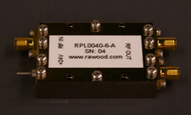
Extreme BW RF Amplifier extended to 3 GHz for Direct Laser Modulation Application
We've extended the frequency range of our extreme BW RF Amplifier from 5 KHz to the upper end of 3 GHz. We customized the input equalizer to create a very flat gain response across the entire band. This amplfier was used for a direct laser modulation application. The measured performance was:
|
|
More information is available from our Extreme BW RF Amplifier page. Let us know if you are interested in this product line! Bob Wood.
Edited on: Wednesday, August 12, 2009 1:37 AM
Categories: 1 Engineering Consulting Services, 4 Hardware Products
Thursday, May 28, 2009
RF Receiver Simulator Delivered
|
We've delivered another RF Receiver simulator to one of our
customers. This unit simulates the RF front end characterisitcs
(noise figure, gain, dynamic range) of an EW system, so the customer
can connect it to their back end system and validate full system end
to end performance (system sensitivity, etc), without requiring the
expensive front end components. Frequency coverage goes from 10 MHz
to 40 GHz on this unit. If you have a need for one of these types of products, please contact us. |
|
Edited on: Sunday, November 01, 2009 11:20 PM
Categories: 1 Engineering Consulting Services, 4 Hardware Products
Sunday, March 01, 2009
Automated RF/Microwave Test Stations designed and delivered
We've been very busy this past year. Over the last 8 months, our super qualified staff have accomplished the following:
|
|
Edited on: Sunday, October 06, 2013 11:53 AM
Categories: 1 Engineering Consulting Services, 2 Software Products and LabVIEW Projects, 4 Hardware Products, 5 Consulting Examples Archive
Wednesday, February 04, 2009
RF and Wireless Courses set up for 2009
We've finally set up our courses for 2009. We appreciate the patience people have shown while we were setting up this schedule. A quick summary of the courses and locations:
- Introductory RF and Microwaves, presented by Bob Wood
- RF Power Amplifiers, Classes A-S, presented by Nathan Sokal
- RF and Microwave Receiver Design, presented by Bob Wood
The courses will be presented in:
- Baltimore, MD in May 2009
- Syracuse, NY in September 2009
- Philadelphia PA in November 2009
More information can be found at http://www.rawood.com/seminars.
We hope to meet you at one of these courses! Thanks again for your
patience.
Bob Wood
Edited on: Tuesday, August 11, 2009 7:30 PM
Categories: 1 Engineering Consulting Services, 3 RF and Microwave Courses
Thursday, December 18, 2008
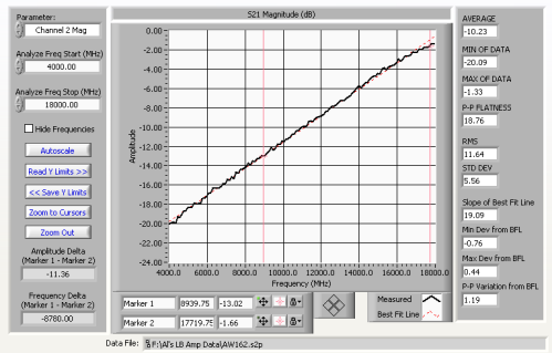
LB RF Amplifier Modules delivered
|
Using our Extreme BW RF amplifiers, we designed, built, and tested
7 LB RF amplifier modules for one of our customers. Our customer's
original vendor failed to deliver their amplifier products and
meet the requirements. So we stepped in and helped them meet their
delivery schedules. These modules were made to "drop in" to our
customer's modules.
These modules will be used in our customer's systems, which will be installed on board Navy vessels. A full set of test data was provided for each LB RF Amplifier Module delivered. Our automated RF test software (RFSpecTest and Painless Extraction) helped to quickly capture the test results and create the test reports. |
|
Edited on: Sunday, March 01, 2009 1:26 PM
Categories: 1 Engineering Consulting Services, 4 Hardware Products, 5 Consulting Examples Archive
Sunday, November 30, 2008
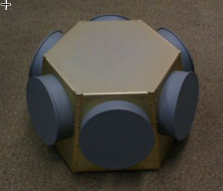
DF Antenna Assembly, designed and built by R. A. Wood Associates
Another great effort resulting in a great potential product!
|
R. A. Wood Associates designed and built a Direction Finding (DF) Antenna Assembly for one of our customers. The Assembly was designed, built, tested, and delivered in less than 6 months. The requirement was to develop an antenna assembly that could be used as a front end in front of a pair of COTS (Commercial Off the Shelf) receiver boards. The DF Antenna Assembly provided the capability to supply Direction Finding (DF) for incoming signals or emitters. The DF Antenna Assembly included:
|
|
Edited on: Tuesday, August 11, 2009 7:31 PM
Categories: 1 Engineering Consulting Services, 4 Hardware Products
Monday, November 03, 2008
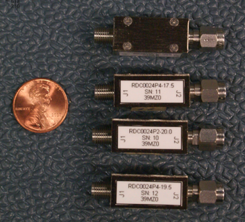
Equalizer Designs now extended up to 18 GHz
Hello Everybody
We've enhanced our portfolio of equalizer designs with new high frequency equalizers, with low losses all the way up to 18 GHz!
We also now have a smaller package design (M02 package).
We can now offer low loss, high linearity equalizers over the following frequency bands:
|
|
Edited on: Wednesday, February 25, 2009 11:24 PM
Categories: 1 Engineering Consulting Services, 4 Hardware Products
Wednesday, October 01, 2008
Electronics Support Switching Unit (ESSU) designed, built, and tested by R. A. Wood Associates
|
R. A. Wood Associates designed, built, tested, and delivered 2 Electronics Support Switching Units (ESSU) to one of our customers. This was another set of hardware slated to to be installed on a Navy Vessel. The ESSU was designed to be installed between the front end (Antennas, RF amplification switching, filtering) and back end (RF processing) of a complex RF/Microwave system. The purpose of the ESSU was to allow a second front end (RF Subsystem 2) to be switched into the same back end, to make use of the RF signal processing in the back end. Some of the major components in the ESSU are as follows:
|
|
Edited on: Monday, November 02, 2009 1:29 AM
Categories: 1 Engineering Consulting Services, 4 Hardware Products, 5 Consulting Examples Archive
Monday, June 30, 2008
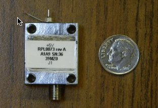
Extreme BW RF Amplifiers
|
We've taken a challenge and come out on top again! We've developed an Extreme BW RF Amplifier, providing ~22 dB gain, and high dynamic range (~36 dBm Third Order Output Intercept Point) over the frequency band of 5 KHz to 2 GHz. An integrated RF package of 1.9" L X 1.3" W X 0.4" H was developed for the Extreme BW RF Amplifier and also included:
The input Equalizer and output Power Divider can be "zeroed out" if not needed. The input Equalizer can be used to compensate for the amplifier slope and/or passive loss slopes. We can provide a variety of RF slopes in the input Equalizer. More information is available from our Extreme BW RF Amplifier page. Let us know if you are interested in this product line! Bob Wood. |
|
Edited on: Sunday, March 01, 2009 1:43 PM
Categories: 1 Engineering Consulting Services, 4 Hardware Products, 5 Consulting Examples Archive
Wednesday, June 25, 2008
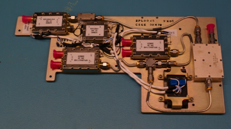
JBU RF Plate Assemblies designed and delivered for Naval Application
|
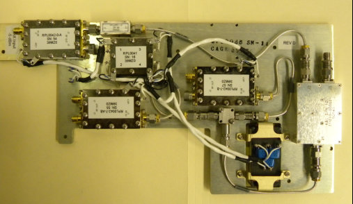
R. A. Wood Associates designed, built and tested and delivered 2
"JBU RF PLate" Assemblies. These RF assemblies were used to
provide wideband gain, equalization, and Built-in-test (BIT)
injection between two very long RF cable runs (between an Antenna
Assembly and below decks receivers). The gain and equalization was
needed to preserve the RF path noise figure and dynamic range
performance through the long cable run.
The exciting part for us is that this design will actually be
deployed on a US Naval vessel. This is our first of several LRU's
that were designed to be used on a US Naval vessel.
|
|
Edited on: Sunday, March 01, 2009 4:02 AM
Categories: 1 Engineering Consulting Services, 4 Hardware Products, 5 Consulting Examples Archive
Thursday, June 19, 2008
New "Equalizers on Demand" RF products available
Greetings! We've been very busy working on creating a new series of RF/microwave products: "Equalizers on Demand". "Equalizers on Demand" are wideband, low loss frequency equalizers made to provide a positive gain slope from the lower frequency to the upper frequency. These equalizers are designed to flatten out slope caused by long cables or other passive losses, or amplifier negative gain slopes. We have developed a wide series of equalizers with various slopes covering the following frequency bands:
- 5 KHz to 2.0 GHz
- 0.5 to 8.0 GHz
- 1.0 to 8.0 GHz
- 1.0 to 2.0 GHz
- 2.0 to 4.0 GHz
- 4.0 to 8.0 GHz
- 4.5 to 12.5 GHz
Equalizers are very important to help your system obtain the best dynamic range performance. You can use them to flatten out a negative gain slope to reduce gain tolerances/differences before going into high dynamic range amplifiers.
We're hoping this series of products create a new paradigm in RF performance. We can provide these very quickly to help correct slope in an RF path, "Equalizers on Demand" can trim RF path slopes almost as easily as attenuators can be used to adjust nominal gains.
These products were developed internally to fill a void in the RF industry. It's very difficult to quickly order a fixed slope equalizer to correct an excessive sloped RF path without waiting 10-12 weeks for delivery. Our losses at the high frequency are the lowest available in the industry. We've searched far and wide to find products with the characteristics of our products, but could not find vendors to supply them. So we bit the bullet (many bullets) and worked on these designs ourselves.
We've worked very hard to make these products easily producible. We can deliver these very quickly (typically 2-4 weeks). If you pre-order an equalizer in a certain frequency band, and then let us know what slope you need, we can most likely incorporate the slope and deliver a tested equalizer within 1-2 weeks.
For more information for the current products and designs available, please visit our "Equalizers on Demand" product page.
We hope we can help improve your RF/Microwave system performance with these products! Bob Wood
Edited on: Monday, June 30, 2008 10:54 PM
Categories: 1 Engineering Consulting Services, 4 Hardware Products, 5 Consulting Examples Archive
Friday, March 21, 2008
Software Manuals Updated and Uploaded
We have updated and uploaded all our software manuals. Many thanks to Amelia, who has been working very hard to create and update all our manuals, and keep them current with our latest software revisions.
Manuals for:
- SpurFinder
- TunerHelper
- RF Path Analysis Toolkit
- RFSpecTest
- Painless Extraction
- Painless Extraction NF
- PathLossSolver
can be downloaded from our Software Products page. Thanks! Bob Wood
Edited on: Monday, June 30, 2008 10:16 PM
Categories: 1 Engineering Consulting Services, 2 Software Products and LabVIEW Projects
Thursday, March 20, 2008
New SpurFinder Version 3.5 Released!
Hi Everybody!
We just released a new enhanced Version 3.5 of SpurFinder. The new version provides the capability to create/load multi-scenario "script" files. The script files can contain multiple SpurFinder scenarios that can be set up for the purpose of evaluating the best spurious conversion scheme. You can "pre" set up the various spur scenarios using Excel or a text file editor, and then save the file as tab-separated text. With a single click of a line in the table, all the scenario information is transferred to the SpurFinder front panel. This allows the user to quickly evaluate many conversion schemes (without having to type all the parameters in the front panel).
You can also modify the SpurFinder front panel information and save the information back to the multi-scenario script file.
It's simple, just load a Multi Scenario Script File, select a row:
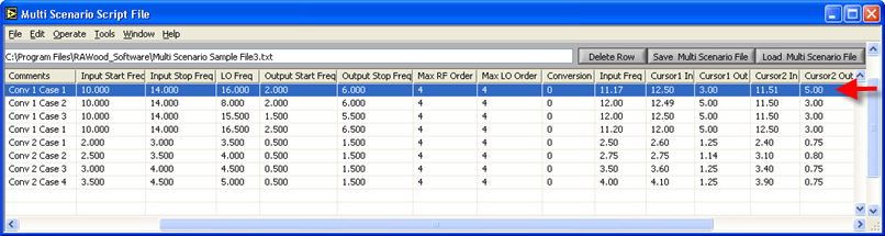
The row information is entered in the SpurFinder Panel:
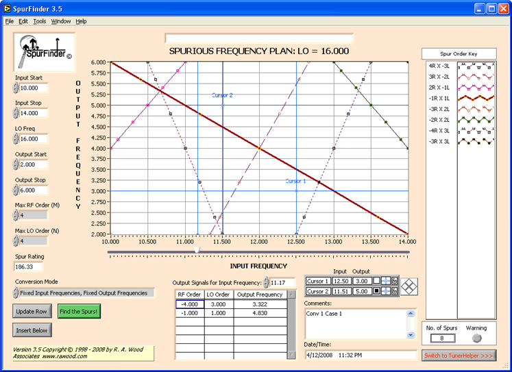
For more information, go to our software page. Download the program, try it out, and let us know what you think. Thanks! Bob Wood
Edited on: Monday, April 14, 2008 7:16 PM
Categories: 1 Engineering Consulting Services, 2 Software Products and LabVIEW Projects
Friday, February 01, 2008
RF and Microwave Course Schedule for 2008 Available
We have published our RF and Microwave course schedule for 2008! We appreciate your patience in waiting for us the set up these courses.
We're offering the following courses:
- Introductory RF and Microwaves
- RF and Microwave Receiver Design
- RF Power Amplifiers, Classes A-S: How the Circuits Operate, How to Design Them, and When to Use Each
The dates and locations are:
- April 2008 in Baltimore, MD
- June 2008 in Boston MA
- September 2008 in Syracuse, NY
- November 2008 in Philadelphia, PA
Please visit our www page for more details
We've added some new improvements to some of these courses:
Introductory RF and Microwaves New Features
We've extended this course to a third day, providing a day of hands-on test and measurements exercises We've added examples of common RF measurements emphasizing the advantages and disadvantages of working with the following microwave test setups:
- Spectral Measurement Setup with signal generators and spectrum analyzer
- Scalar/Network Analyzer Setup
- Power Meter Setup
Since we've added this new section, people have told us that this really helps solidify the concepts presented in the course notes. People who haven't had a chance to work with microwave devices and test equipment obtain a better understanding of the world of RF and Microwaves.
RF and Microwave Receiver Design New Features
We've added and additional 1/2 day to this course, with more hands-on examples of using software to perform receiver design tasks. This enhances our Receiver Design Problem we follow throughout the course.
We look forward to seeing you at one of these courses! Bob Wood
Edited on: Saturday, April 12, 2008 10:24 PM
Categories: 1 Engineering Consulting Services, 3 RF and Microwave Courses
Sunday, November 04, 2007
RF Receiver Simulator Delivered!
Hello Everybody
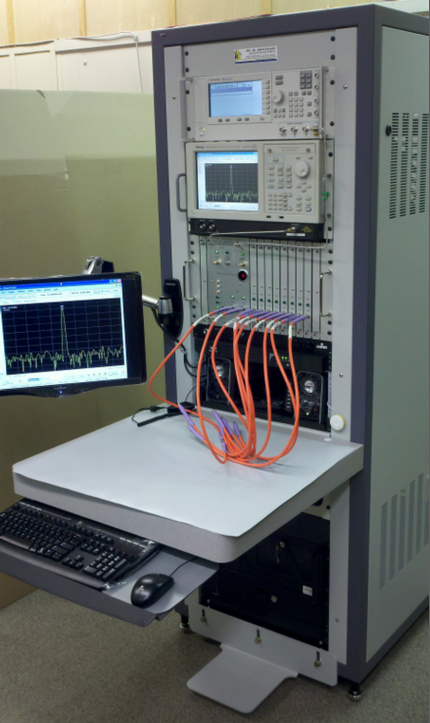
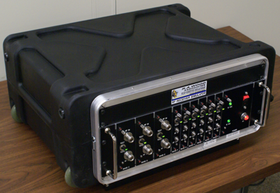
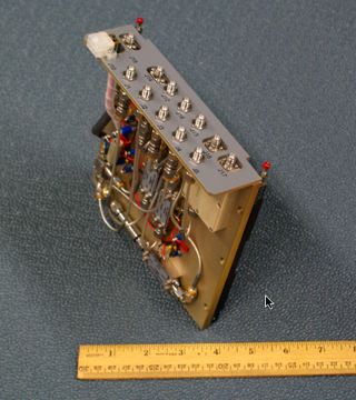
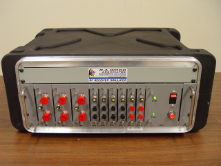
We just delivered our latest product: a multi-channel RF/Microwave Receiver Simulator. This device simulates the RF front end of an ESM (Electronic Support Measures) system. The simulator matched the noise figure, gain and dynamic range of the RF front end. The simulator contained 9 channels of RF bands covering from 10 MHz all the way up to 40 GHz.
Some pictures of the RF Receiver Simulator are shown below. The RF Receiver Simulator is a 3U rack-mounted assembly mounted in a protective roll-away cart for ease of transportability.
Edited on: Monday, June 30, 2008 10:16 PM
Categories: 1 Engineering Consulting Services, 4 Hardware Products, 5 Consulting Examples Archive