« 3 RF and Microwave Courses | Main | 5 LabVIEW Examples Archive »
Sunday, November 04, 2007
RF Receiver Simulator Delivered!
Hello Everybody
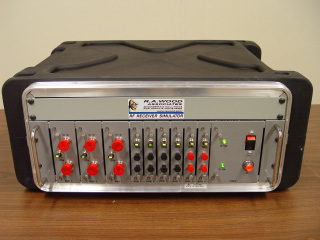
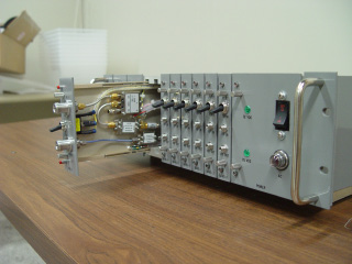
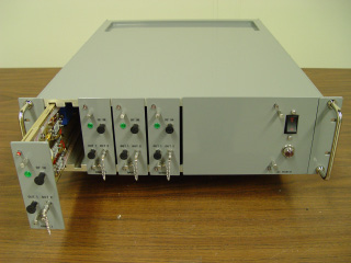
We just delivered our latest product: a multi-channel RF/Microwave Receiver Simulator. This device simulates the RF front end of an ESM (Electronic Support Measures) system. The simulator matched the noise figure, gain and dynamic range of the RF front end. The simulator contained 9 channels of RF bands covering from 10 MHz all the way up to 40 GHz.
Some pictures of the RF Receiver Simulator are shown below. The RF Receiver Simulator is a 3U rack-mounted assembly mounted in a protective roll-away cart for ease of transportability..
Edited on: Sunday, November 04, 2007 8:39 PM
Categories: 1 Engineering Consulting Services, 4 Consulting Examples Archive
Wednesday, September 12, 2007
EW Receiver Simulator designed, built, tested, and delivered
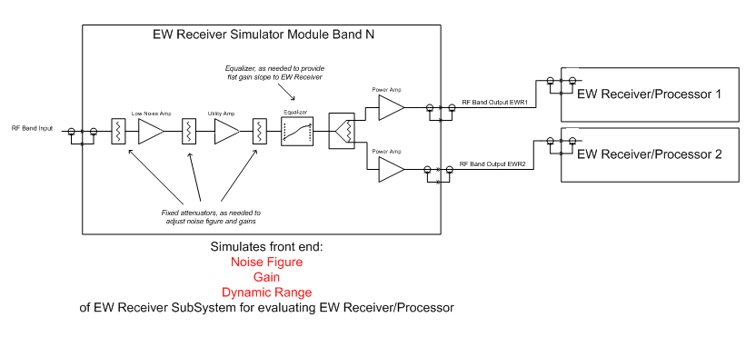
'We just delivered an EW Receiver Simulator to one of our customers. The simulator provided the simulated RF and microwave front end performance of an EW (Early Warning) Receiver subsystem. Our simulator allows the EW Receiver/Processor to be evaluated without requiring the actual front end system. The simulator was designed to match the system front end noise figure, gain, and dynamic range. This also represents a new modular and mechanical design for us.
A block diagram of one channel of the EW Receiver Simulator is shown below:
Edited on: Sunday, November 04, 2007 10:41 PM
Categories: 1 Engineering Consulting Services, 4 Consulting Examples Archive
Thursday, January 04, 2007
RF Power Amp Automated Test Software and Test Fixure designed and delivered
Hello Everybody
We just wanted to let you know about another quick turn-around software development and mechanical test fixture design example.
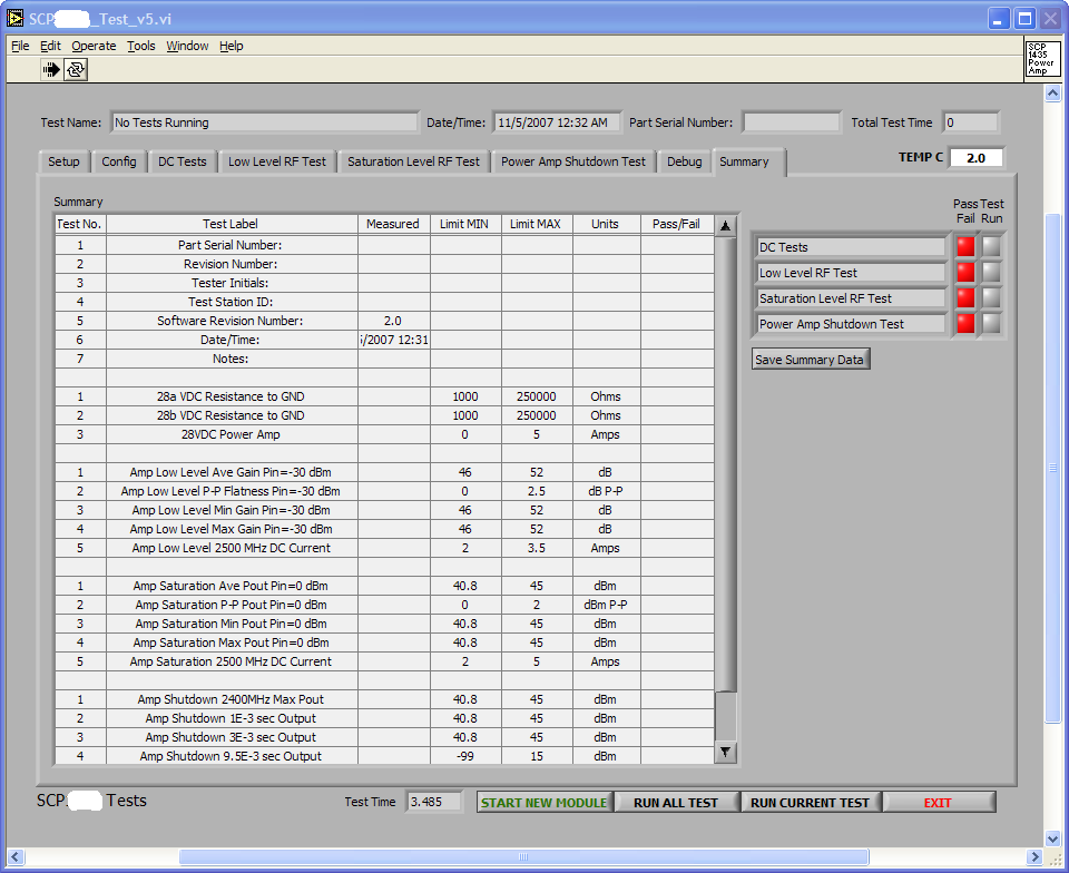
We were tasked to provide a quick development of automated test software for an 30 Watt RF power amp. All software tests (gain, output power, pulse On/Off capability were developed very quickly using the built-in capabilities of RFSpecTest. The test panel user interface is shown below (note: this display is before the test has been run).
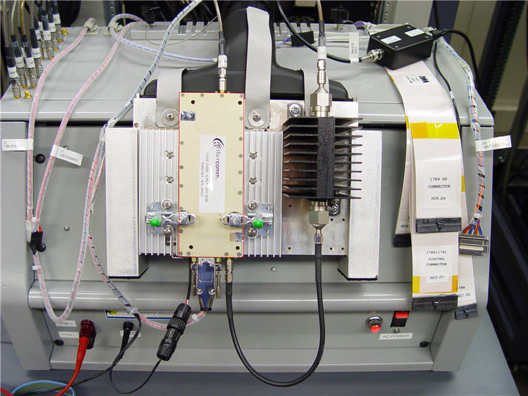
As part of this effort, we also developed a quick release test fixture so we could quickly connect, test, and disconnect the RF Power Amplifier. A picture of the power amplifier test fixture, integrated into our automated test fixture, is shown below. The Amplifier Under Test" is located between the heat sinks, and is kept in contact with the test fixture plate with the green toggle clamps shown. The thermal challenge was to make sure the amplifier was kept reasonably cooled while mounted in the test fixture. A squirrel cage fan inside the ATE rack provided cooling air to the test fixture via the black plenum shown. Heat sinks were located on each side of the power amplifier, and underneath the power amplifier on the other side of the test fixture plate. The RF amplifier provided up to 32 Watts of RF power, and used about 140 Watts of DC power. Both software development and the mechanical test fixture worked great.
Just another example of what we can do for our customers! -Bob Wood
Categories: 1 Engineering Consulting Services, 2 Software Products, 4 Consulting Examples Archive, 5 LabVIEW Examples Archive
Monday, December 18, 2006
RAQ I/O 8-8-8-8 Design completed and delivered
Hello fellow ATE solution providers and purchasers,
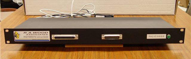
We needed to add additional I/O and switching capability for one of our test station designs. We didn't want to have to retrofit our original automated test fixture design, so we came up with a simple 1U rack mount design that added the following capabilities to our ATE test station:
- 8 Digital Outputs (TTL)
- 8 Digital Inputs (TTL)
- 8 Relays (for switching power and meter signals)
- 8 Analog Inputs (0-5 Volts in 0-1000 quantization levels)
- Simple USB interface to Test Station PC for control
- I/O and switching controlled via LabVIEW software
- All interfaces through front panel 37 pin and 25 pin standard D-shell connectors
- Only 1U of Rack space used
Below is a picture of the RAQ I/O 8-8-8-8. If you would like us to build one for you, or provide a customized solution for your needs, just let us know!
-Bob Wood
Edited on: Sunday, November 04, 2007 10:38 PM
Categories: 1 Engineering Consulting Services, 4 Consulting Examples Archive, 5 LabVIEW Examples Archive
Friday, September 15, 2006
New Integrated RF Test Rack Designed and Delivered
On September 15 2006, R. A. Wood Associates delivered the first two of 15 complete Integrated RF Test Racks. The Integrated RF Test Rack provided a complete solution for complete automated testing of 7 RF/Digital modules. All equipment was controlled through GPIB interfaces. All automated test software was written in National Instruments LabVIEW by R. A. Wood Associates. RFSpecTest was used in "script" mode to perform most of the RF measurements. The rack consisted of:
- 2 Signal Generators (one for RF signals, one for LO signals)
- 1 Spectrum Analyzer (for measuring RF signal amplitudes and frequencies)
- 1 Multimeter (for monitoring resistances and voltages at various points on the modules)
- 3 Power Supplies (for providing DC power to the modules under test)
- A rack mount PC with GPIB and Digital I/O cards, loaded with software for controlling test equipment and reporting test results
- A rack mount interruptible power supply (UPS)
- R. A. Wood Associates Automated RF Test Fixture
- Laser Bar Code Reader (for reading and automatic entry of module serial numbers)
- A 19" Flat Panel Display (mounted on movable monitor arm)
- Keyboard and Mouse in a slide-out ergonomic tray
The full rack was designed to be a comfortable testing environment, as well as easy to maintain. Equipment is easy to remove if needed with minimal interference to other equipment.
More information about the Integrated RF Test Rack is available from this link.
Edited on: Sunday, November 04, 2007 10:22 PM
Categories: 1 Engineering Consulting Services, 4 Consulting Examples Archive, 5 LabVIEW Examples Archive
Friday, December 02, 2005
New Computer Automated RF Test Station developed and delivered
We designed and developed a Computer Automated RF Test Station for one of our customers. The Computer Automated RF Test Station is capable of testing 7 different RF and RF/digital modules, but is flexible enough to test many possible RF modules. The Test Stations were built and tested at R. A. Wood Associates. Computer automated test software was also developed to test the 7 different modules using LabVIEW. RFSpecTest was used in a "scripted" mode to perform all RF tests. More information about the Computer Automated RF Test Station is available at this link.Edited on: Sunday, November 04, 2007 10:27 PM
Categories: 1 Engineering Consulting Services, 2 Software Products, 4 Consulting Examples Archive
Sunday, April 17, 2005
New RF Receiver Simulator Delivered
We delivered a wideband RF/microwave Receiver Simulator to one of our clients on March 1. The simulator was designed to simulate the front end of an RF/Microwave system. Frequency coverage went from HF to SHF Ka Band. The simulator was required to have very low noise figures and very high intercept points/compression points. The unit was delivered in 6 months after order. More information is available at this link location.Edited on: Monday, August 14, 2006 2:46 AM
Categories: 1 Engineering Consulting Services, 4 Consulting Examples Archive
Saturday, June 01, 2002
Upgrade and Repair Services
Upgrade and Repair Services
- One of our clients had received some RF modules that were functionally working, but the performance was not meeting system performance requirements. We analyzed the modules, determined the changes needed to meet system performance requirements, and upgraded the RF modules for our customer. Some of the highlights of this effort:
- New RF components were specified, sent out for quotes, and purchased from vendors
- Improved 1 dB compression points
- Reduced noise power levels
- Improved P-P flatness
- Automated RF test software was developed to perform final acceptance tests
- Acceptance test reports were created and delivered to the customer for each upgraded RF module
- Some of the modules were RF components interconnected with coaxial RF cables
- Some of the modules were surface mount components on microstrip medium
- The system performance was greatly enhanced by these upgraded RF modules
Edited on: Monday, August 14, 2006 1:40 AM
Categories: 4 Consulting Examples Archive
Monday, October 01, 2001
Filter Design Study
Filter Design Study
- We helped a customer analyze a filter specification and provide a filter design that would be producible and come as close to the filter specification as possible. The end result was that the filter requirements were not fully realizable. This enabled the customer to revise their design approach so that a more realizable filter could be utilized, thereby preventing them from going forward with a system design that was not feasible
Edited on: Monday, August 14, 2006 1:10 AM
Categories: 4 Consulting Examples Archive
Friday, June 01, 2001
Computer Automated Test System for LDMOS Wireless RF Power Amplifiers
Computer Automated Test System for LDMOS Wireless RF Power Amplifiers

- We provided an automated RF Test System to provide computer automated testing of LDMOS RF Power Amplifiers. The amplifiers are used in base stations for AMPS, PCS, UMTS systems. Software was developed using National Instruments LabVIEW
- RF Measurements provided at several Output Power Levels
- Gain
- Gain Compression (servoed to X dB gain compression)
- Output Power (servoed to a specified power)
- Intermodulation Products (IMD)
- Adjacent Channel Power (ACP)
- Return Loss
- DC Measurements included:
- IDQ Servo (Adjust Vgg to achieve desired Idd current)
- Idd measurement at RF Output Power
- Ronq
- Ronh
- Gmq
- Gmh
- Other Measurements
- Efficiency
- Power Added Efficiency (PAE)
- For an overview presentation of the LDMOS Automated Test System:
Edited on: Monday, August 14, 2006 1:36 AM
Categories: 4 Consulting Examples Archive
Saturday, January 01, 2000
Satellite Communication Phased Array Solid State Transmitter Design
Satellite Communication Phased Array Solid State Transmitter Design
- Spreadsheet modeling of RF signal paths and RF path parameters
- Developed specifications for RF components
- Performed requirements analysis and specification flow down
- Developed a "B2 Level" specification for the microwave assembly
Edited on: Monday, August 14, 2006 2:20 AM
Categories: 4 Consulting Examples Archive
Saturday, May 01, 1999
Cable TV System Model to Predict Linear and Nonlinear Performance from Headend to the Home
Cable TV System Model to Predict Linear and Nonlinear Performance from Headend to the Home
- We developed a CATV system model to predict performance from the CATV Headend to the Home
- Performance predictions included:
- Carrier to Noise (C/N)
- Composite Triple Beat (CTB)
- Composite Second Order High (CSOhigh)
- Composite Second Order Low (CSOlow)
- Amplitude Levels vs Frequency
- Slope
- Channel Plans Analyzed:
- 79 Channel
- 95 Channel
- 112 Channel
- 125 Channel
- Other Parameters...
- An example spreadsheet printout (Adobe Acrobat pdf format) is shown here, showing 6 cable spans and amplifiers
- Individual Components and their associated parameters were created and added to a component database. The database tracked over 900 RF component parameter fields for various components used in the cable TV industry. The initial database contained over 800 components, with capability of adding thousands more components. Data could be imported into the database from files created by other programs (S2P files, for example).
Edited on: Monday, August 14, 2006 12:45 AM
Categories: 4 Consulting Examples Archive
Sunday, November 01, 1998
MetalTest Software
MetalTest Software
A software program was developed using LabVIEW, a graphical programming language from National Instruments. The program runs on a PC and is connected to an Acromag Metal Tester using a PC Data Acquisition board. The program compares the readings gathered from the Metal Tester to readings in a database for various alloys. The program then gave a readout of what metal alloy most closely coincided with the metal being tested. The program also provided probability levels (T-Test) to show confidences against the various other possible alloys in the database. The MetalTest System is currently being used to recycle aircraft engine machining scrap and is helping the company earn hundreds of thousands of dollars in metal reclamation sales.
Click here for more information!
Edited on: Monday, August 14, 2006 1:32 AM
Categories: 4 Consulting Examples Archive
EW System Analysis and Support
EW System Analysis and Support
- We helped a customer with system design, analysis and support for a naval surface ship EW system over a 3 1/2 year period. Some of the key points of this effort:
- Developed specifications for EW subsystems, WRA's, SRA's, and RF components
- Developed analysis programs to predict system performance and specify from subsystems down to components
- Helped investigate new technologies for various subsystems, such as RF delay lines, RF channelizers, etc.
- Attended vendor design reviews and meetings to support the customer
Edited on: Monday, August 14, 2006 2:20 AM
Categories: 4 Consulting Examples Archive
Saturday, August 01, 1998
IF Receiver/Digitizer
Engineering Consulting Examples: IF Receiver/Digitizer
Software was developed to retrieve the binary data from a IF Receiver/Digitizer board. The board design utilized a 10 MHz A/D converter to sample the IF signal. A Logic Analyzer attached to the board captured the digital data from the IF Receiver/Digitizer board. The computer used an IEEE-488 interface to connect to the Logic Analyzer and retrieve the values. After the binary data was retrieved, converted, and stored in an array, the data could be graphed and analyzed. The arrays were converted to a series of voltage values of the incoming signal. The voltages were plotted and then recorded. The data was then used in signal frequency and noise analysis. The Fast Fourier Tranform was used to determine the spectral content of the sampled signals. The FFT of the digital signal could then be compared to the Power Spectrum Analyzer data of the analog signal. The software was developed using National Instruments LabVIEW graphical programming language. The measured data could be stored to a data file to record that particular test.
- Click here to see display panel showing A/D Noise Floor Measurement
- Click here to see display panel showing A/D Measurement of 4 MHz Signal
- Click here to see display panel showing A/D Measurement of 17 MHz Signal
Edited on: Monday, August 14, 2006 1:14 AM
Categories: 4 Consulting Examples Archive
Sunday, February 01, 1998
Cryogenic Cooled RF Amplifier Development for PCS Application
Cryogenic Cooled RF Amplifier Development for PCS Application
- We helped a company involved in Cryogenic packaging to design, verify and test a cryogenic cooled LNA package. We used LabVIEW software to develop a complete computer automated test station, providing the following measurements controlled by LabVIEW via GPIB interfaces:
- Full 2-Port S-Parameters
- Noise Figure vs. Frequency
- 1 dB Output Compression Point vs Frequency
- Two Tone Third Order Output Intercept Point vs Frequency
- The test setup was designed so that a lot of detailed testing could be completed in a very short time (while the device was in a vacuum and being cooled with liquid Nitrogen. The test equipment being controlled included:
- HP Network Analyzer
- HP Noise Figure Meter
- HP Power Meter
- HP Signal Generator
- HP Spectrum Analyzer
- All measured data was stored electronically in electronic format for importing into spreadsheet programs for further analysis and plotting of results.....
Edited on: Monday, August 14, 2006 12:48 AM
Categories: 4 Consulting Examples Archive
Thursday, January 01, 1998
High Speed Synthesizer for Medical Monitoring Equipment
High Speed Synthesizer for Medical Monitoring Equipment
The figure above is a simplified block diagram of a high speed synthesizer developed by R. A. Wood Associates for a medical application. Some of the preliminary specifications are shown below:
- Output RF Power:
- The output RF power in to 50 ohm load shall be 3 Watts minimum
- Output VSWR
- 1.7:1, 50 Ohm reference impedance.
- Frequency Source Requirements
- The RF source shall provide 2 selectable frequencies (Frequency 1 and Frequency 2). The frequencies are selected based on the logic level applied to the Freq Change Strobe. When the Freq Change Strobe is logic 0, the output frequency shall be at Frequency 1. When the Freq Change Strobe is Logic 1, the output frequency shall be at Frequency 2.
- Frequency Range
- The output frequency range shall be 80 to 120 MHz.
- Frequency Resolution
- The frequency resolution of the source shall be less than 1 KHz
- Spurious (In-band)
- The maximum level of spurious signals within the frequency range of 60 MHz to 160 MHz shall be -30 dBc relative to the RF output signal level.
- Harmonics and out of Band Spurious
- The maximum level of harmonics and spurious signals outside the frequency range of 60 MHz to 160 MHz shall be -20 dBc.
- Digital Interface:
- Serial Interface, 2 wire, Clock and Serial Data
- Power Level Control
- Analog Input for Power Control: 0 to 10 Volts, approximately linear, to adjust RF power from 1 to 3 Watt
- Frequency Switching Time:
- Less than 5 uSec (actual performance is less than 10 nSec)
Edited on: Monday, August 14, 2006 12:50 AM
Categories: 4 Consulting Examples Archive
Monday, September 01, 1997
RF Wireless Link for 915 MHz ISM Band
RF Wireless Link for 915 MHz ISM Band
- We provided a quick turnaround prototype design for a customer. The project involved designing a wireless link for sending and receiving digital data. The transmitter used FSK modulation at 915 MHz to send the digital information. The transmit power levels were restricted to less than 1 mW. The receiver provided front end filtering, low noise amplification, and demodulation of the FSK signals to digital information. Most of the components used were RF integrated circuits from RF Micro-Devices. The link was field tested also.
Edited on: Monday, August 14, 2006 1:25 AM
Categories: 4 Consulting Examples Archive
Saturday, June 21, 1997
Software Controlled Laser Power Meter Interface
Software Controlled Laser Power Meter Interface
- Software was developed to provide a computer-controlled interface to a Universal Radiometer. The Universal Radiometer is a piece of test equipment used to measure laser power. The device was controlled by a PC serial port. The software was developed using National Instruments LabVIEW graphical programming language.
- All instrument controls are sent from the screen display through the PC serial port to the test equipment.
- Data from the test equipment is sent via the PC serial port to the computer and analyzed and displayed on the screen display.
- Measured data can be stored to an external file in Microsoft Excel or other spreadsheet compatible format.
- Measurement statistics are calculated and displayed in real time
Edited on: Thursday, July 20, 2006 4:38 PM
Categories: 4 Consulting Examples Archive, 5 LabVIEW Examples Archive
Sunday, September 01, 1996
RF System Design for F-22 Electronic Warfare (EW) System
RF System Design for F-22 Electronic Warfare (EW) System
- RF System Performance Predictions and Specification Development
- Develop RF system analysis models to specify and predict RF system performance
Edited on: Monday, August 14, 2006 12:53 AM
Categories: 4 Consulting Examples Archive
Wednesday, May 01, 1996
Noise Figure Computer Automated Test
Noise Figure Computer Automated Test
- The Need:
- A customer was using an existing computer automated test software to provide noise figure measurements for RF amplifiers. The program was written in HP BASIC, and the software was run on an older HP computer. The software was antiquated and not user-friendly, the computer was aging and unreliable (used 5 1/4 inch floppies, etc). The test setup was limited to about 750 MHz in frequency coverage.
- The amplifiers were used for CATV distribution amplifiers, and the test setup was used by Incoming Inspection and Test to verify specification compliance.
- The Customer wanted to upgrade the software to HT BASIC, replace the computer with a newer PC compatible computer, provide a better, more user-friendly interface, allow different devices to be tested to different specifications, and increase the measurement capability to provide accurate measurements up to 1000 MHz.
- The Solution:
- R. A. Wood Associates transferred the existing software over to HT BASIC, which was then developed on a PC compatible computer. The software was completely re-written to provide a menu-based test setup, where the user could select parameters for calibration, test, and set up specification limits. Once the test parameters were set up, the test person could just insert the devices into a "quick connect" fixture and push the "TEST" button for quick verification.
- A user-friendly test interface was designed and implemented.
- The test procedure was revised using improved test and calibration techniques to provide accurate noise figure and gain measurements for frequencies up to 1500 MHz.
- Other Points to Make:
- The software was developed at R. A. Wood Associates, and installed and verified at the customer's location.
- User-defined test and calibration frequencies allowed the operator to greatly reduce test time
- which helped save money for the customer.
- The software was designed to be user-friendly:
- A menu based structure was designed.
- New test parameters could be easily be added.
- Press "RETURN" for default parameters saved re-typing current parameters.
- The software was structured for minimal maintenance and easy upgrades.
- A complete user documentation package was provided to the customer for training purposes.
- The test setup used HPIB interfacing and HP 8970A Noise Figure Meter.
- The setup was designed to test devices in a 75-Ohm environment.
- For the entire effort, we kept the customer's needs in mind as a primary objective.
Edited on: Monday, August 14, 2006 2:13 AM
Categories: 4 Consulting Examples Archive
Monday, April 01, 1996
HP BASIC Software to Provide Test Interface to Micro-controller
HP BASIC Software to Provide Test Interface to Micro-controller
HT BASIC Program for controlling an on-board micro-controller through a PC serial port interface. This was to be used in an automated test environment.
Edited on: Monday, August 14, 2006 1:22 AM
Categories: 4 Consulting Examples Archive
Monday, January 01, 1996
Subcontract Specification Development
Subcontract Specification Development
A commercial manufacturer needed to develop a subcontract specification for an integrated RF assembly which they wanted to send out for quotations, and subcontract the design and development services. R. A. Wood Associates analyzed the requirements for the device based on its "system" application, and developed a 25 page specification for the device. All this occurred to meet a rush deadline in about 3 weeks time. More info to be provided...
Edited on: Monday, August 14, 2006 2:08 AM
Categories: 4 Consulting Examples Archive
Tuesday, August 01, 1995
Wireless Components Research
Wireless Components Research
Provide research and quotes for wireless components including low noise RF amplifiers, ceramic filters, base station duplexers in the cellular frequency bands.
Edited on: Monday, August 14, 2006 1:17 AM
Categories: 4 Consulting Examples Archive